
Deploy NSX Edge Nodes in VCF 9
Walk through NSX Edge deployment in VCF 9, including networking prerequisites, edge nodes, BGP uplinks and lab-specific deployment notes.
Overview
This NSX Edge deployment walkthrough uses vCenter in my VCF 9 lab to connect virtual networking to a physical UniFi router. It covers the networking inputs, Edge nodes and BGP uplinks that I prepared before configuring a VPC.
Network worksheet and completion checks
| Input | Record before deployment |
|---|---|
| Edge management | Two distinct FQDNs and management IPs; subnet, gateway, DNS and NTP; placement and credentials. |
| TEP network | Edge TEP VLAN, DHCP/pool/static allocation and reachability to host TEPs; verify the chosen MTU end to end. |
| Uplinks | Transit VLAN/subnet, local Edge uplink IPs, upstream router addresses and physical NIC mapping. |
| Routing | Local and remote AS numbers, neighbor pairs and allowed advertised/received prefixes. Keep these separate from management IPs. |
| Consumption | VPC public/private ranges, overlap checks and the Edge form factor/HA mode required by the intended Supervisor and Automation release. |
- Wait for both Edge nodes to report successful configuration and Up status; verify transport/tunnel health.
- Check the Tier-0 gateway, neighbor sessions and expected learned routes. An enabled BGP configuration alone is not evidence of an established session.
- Test a permitted VPC-to-upstream path and return traffic; review NAT/firewall rules if one direction fails.
Unsupported hardware: the Ryzen CPU-check modification mentioned below bypasses a compatibility check. It does not make the CPU supported. Keep that experiment in an isolated, disposable lab; use compatible hardware for a supported deployment.
Networking prerequisites
To complete this deployment you will need a VLAN for the NSX T0 gateway which is the uplink used to communicate with the physical network, you will also need a dynamic or static routing configuration on your physical router. I am going to be using BGP for this environment, you can also you OSPF for dynamic routing.
I already have my Unifi dream machine pro router configured for BGP so I just need to configure the virtual side for them to start routing traffic. If you have this router in your environment and don’t have BGP setup, follow my post to configure the unifi router.
Prepare NSX networking
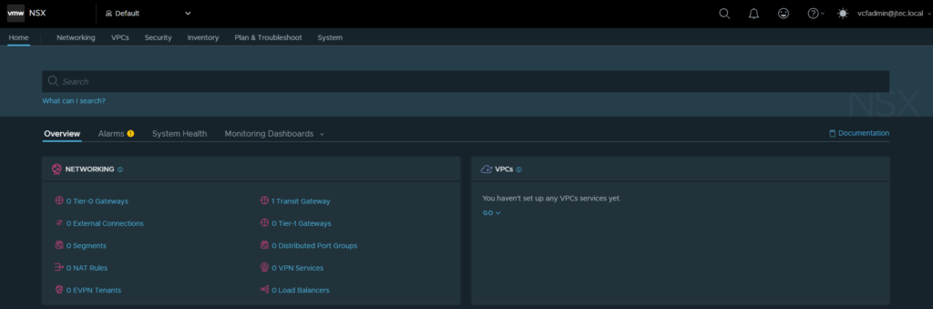
First we will need to login to our NSX manager with an enterprise admin privileged account.
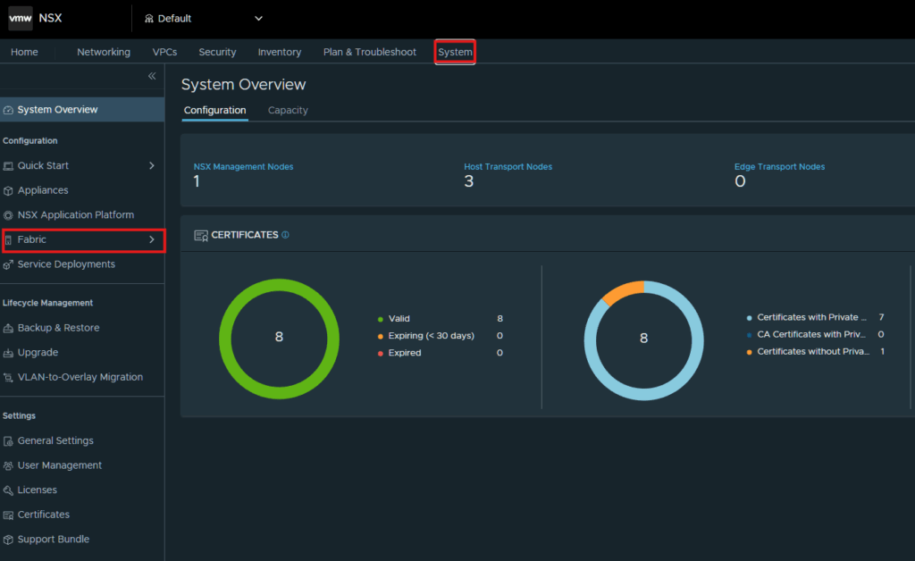
Click on System > Fabric.
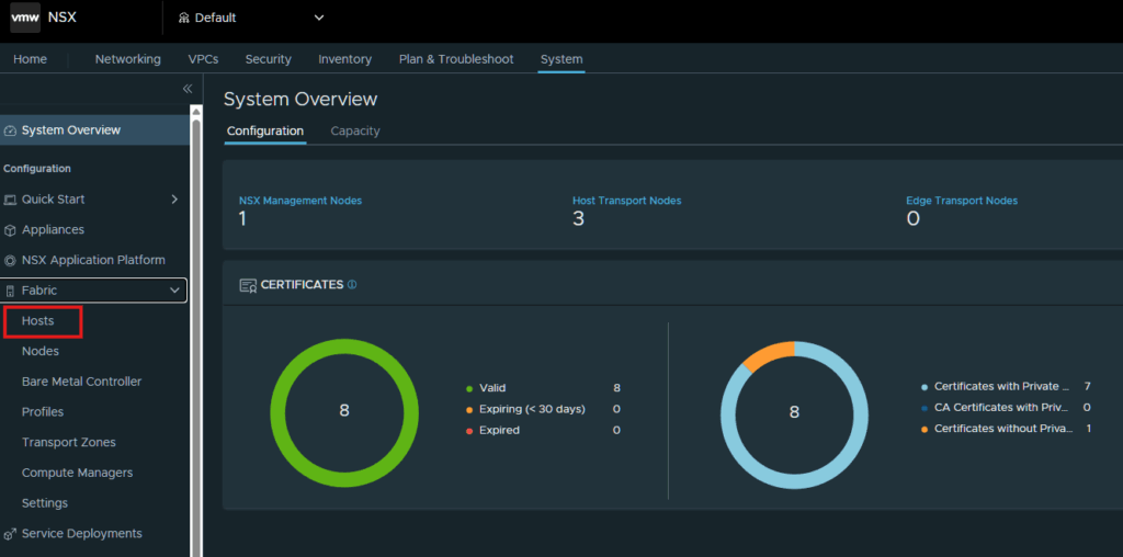
Select Hosts
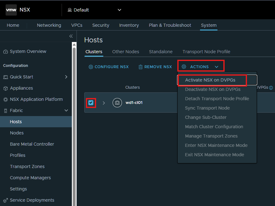
Click the checkbox next to the vSphere host cluster and click Actions > Activate NSX on DVPGs.
In the pop-up click Yes
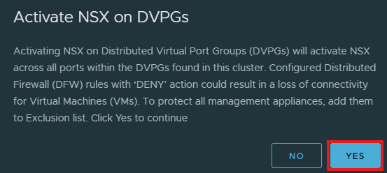
Configure network connectivity
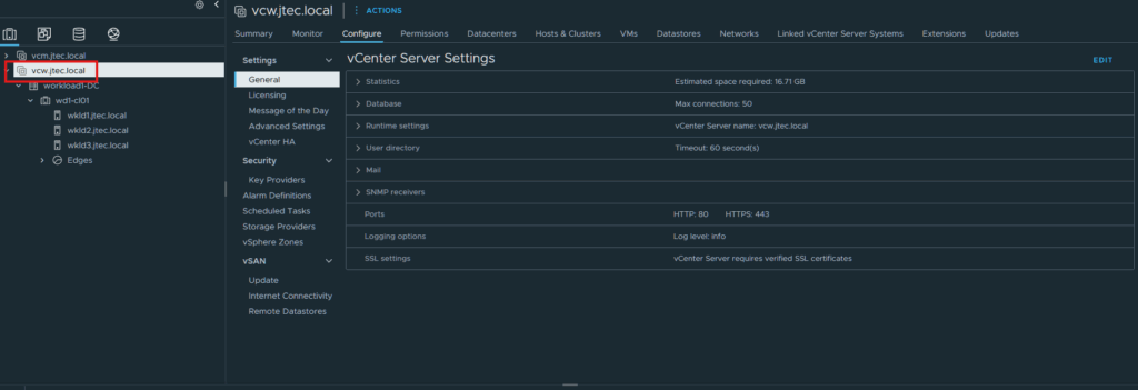
Now we have to login to the vCenter Server and click on the vCenter server object.
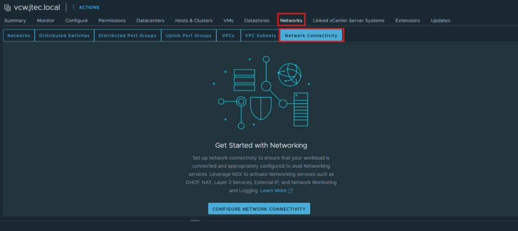
Select Networks > Network Connectivity.
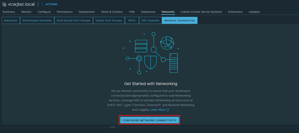
Click Configure Network Connectivity.
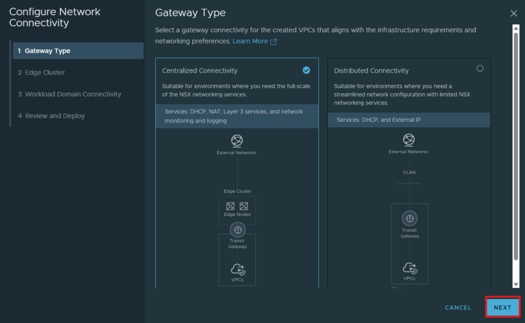
Centralized Connectivity is the default gateway selected, this is what I am going to use as I want to build an edge node cluster and use all services available. Click Next.
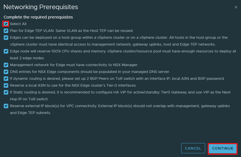
Review the Networking Pre-requisites for deploying NSX edge nodes, and click the checkbox next to Select All and click Continue.
Configure the Edge nodes
We will be deploying 2 NSX Edge nodes that will require DNS entries, Management IPs, BGP routing IPs, Edge Tunnel Endpoint VLAN (TEP) as well. Please ensure you have this setup prior to completing this deployment.
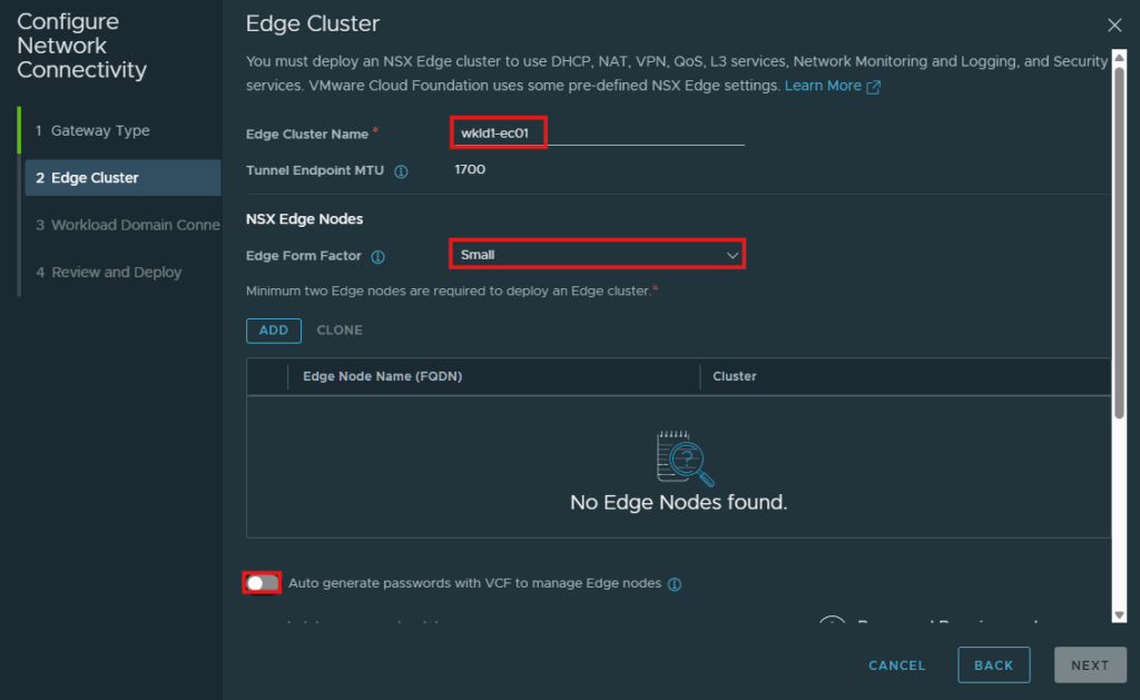
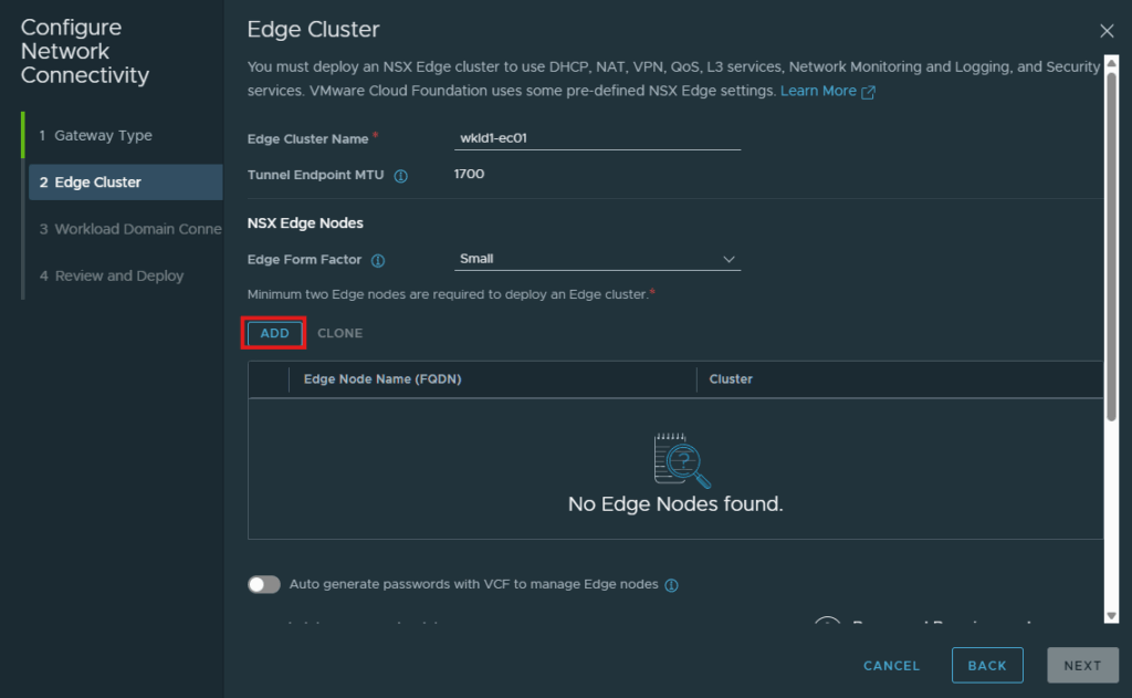
Enter in the Edge Cluster Name, and select the Form Factor for your nodes. You can use an auto-generated password for this nodes of create your own. I will be creating my own by click the slide at the bottom and filling in the passwords below that.
Originally I tried to deploy small form factor NSX edges and realized that you need to have a minimum of Medium form factor for vSphere Supervisor.
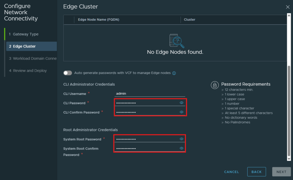
After entering in that information, return to the top and click Add to add the edge nodes.
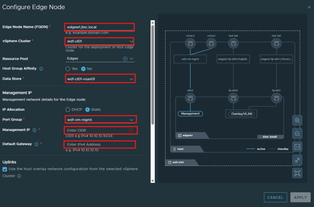
At the Configure Edge Node screen, you will need to enter in the relevant information to your environment for the deployment. I am choosing to use a static IP for management.
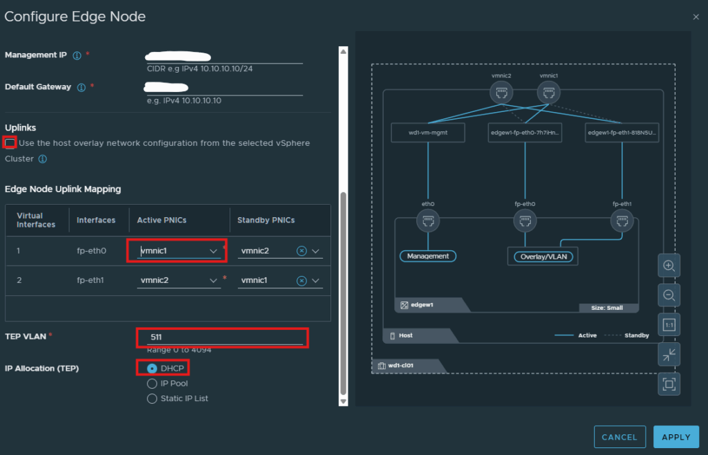
I also have a separate vlan for the Edge TEPs, so I unchecked the box underneath Uplinks. Then enter in the VLAN id for my TEP and I also have DHCP setup for this, you can use an IP Pool or Static IP list. You also have to select the Active PNICs for the edge nodes.
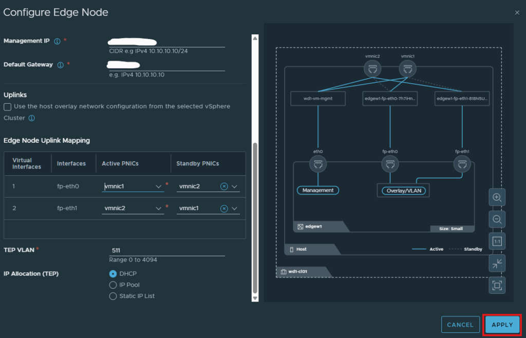
After you have completed entering in the deployment information, click Apply.
Repeat the steps above to add an additional Edge node. I clicked the radio button next to my edge node and used the clone option which will ask for a new management IP and FQDN for the second edge node but use the same information you entered previously.
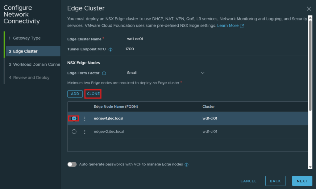
Once you have at least 2 NSX Edge nodes configured for deployment, click Next.
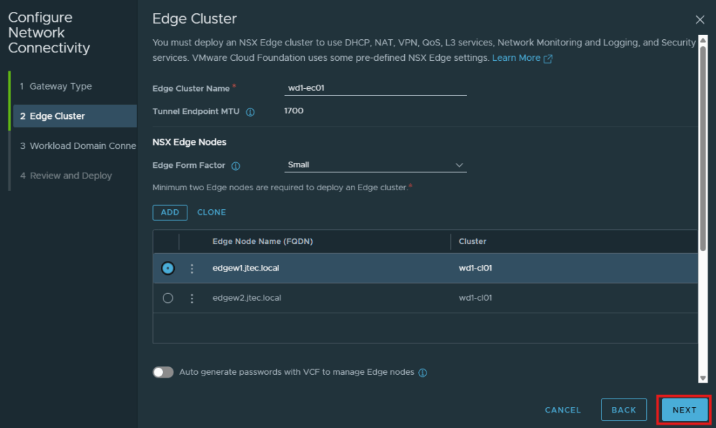
Configure routing and deploy
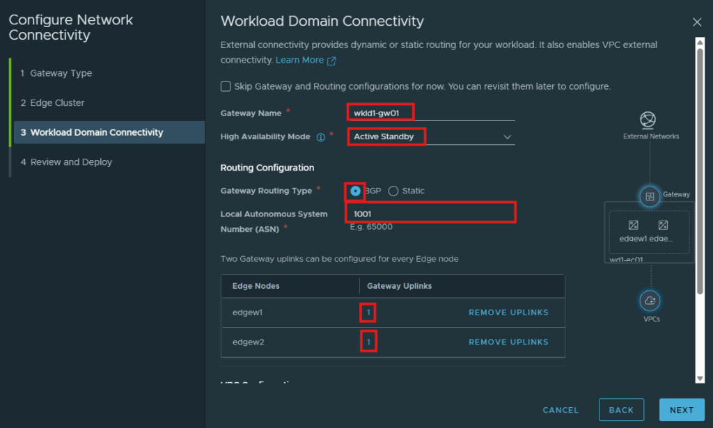
For the domain connectivity you can skip the gateway and routing configuration for the edge deployment, I already have BGP setup on the physical so I enter in my gateway name, bgp routing configuration, gateway uplinks and my VPC subnets. Click Next to review
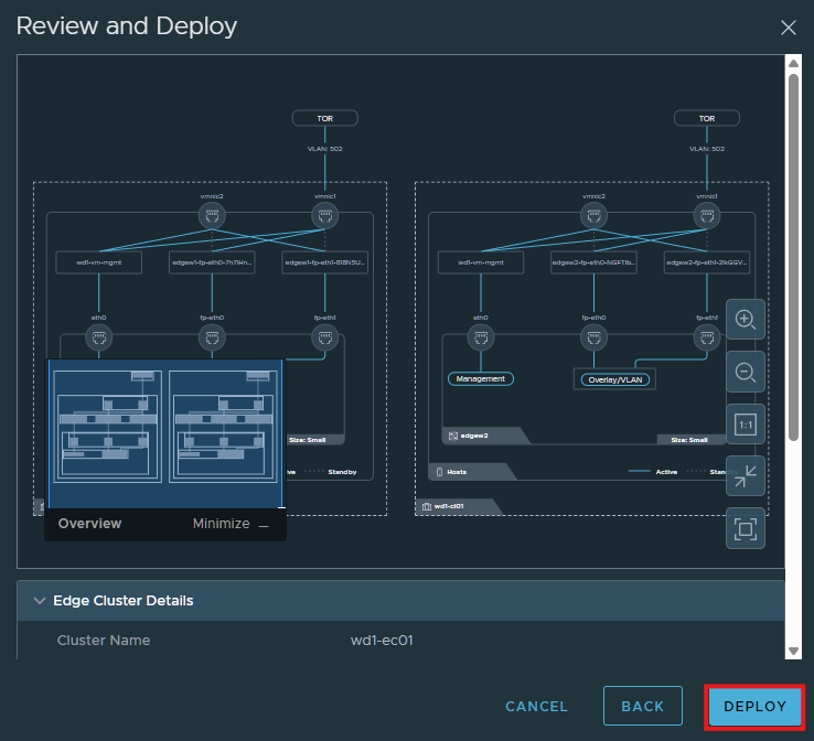
For High Availability Mode, I have selected Active/Standby which I understand is required for vSphere Supervisor and Automation and I will be configuring those later on.
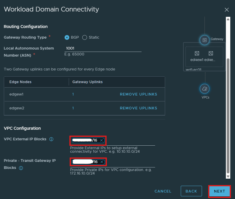
Click Deploy to have the edges deploy.
Lab hardware considerations
The Ryzen remediation experiment modifies a CPU compatibility check. It is unsupported and lab-only; do not treat it as a production deployment prerequisite.
Check out my other VMware Cloud Foundation 9 Lab posts.